Most TV or FM antenna projects require a matching impedance cable(balun) but how to make a 75 to 300 ohm matching transformer?
Well, you might not be an electric engineer but still, you can easily make one at a very affordable rate.
With the help of this simple electronic device, you’ll be able to connect your antenna with a coaxial cable. What is a coaxial cable?
It is a type of cable which can carry high-frequency waves without giving much loss of electrical energy.
Sounds complicated? Don’t worry we’ll talk about baluns and their applications in this article.
We’ll also describe the procedure by which you can make one for yourself. So without any further delay, let’s get right into it.
What is a 75 to 300-ohm matching transformer?
At first, let’s learn what is a matching transformer or impedance matching transformer?
Impedance matching transformer is also known as balun is an electronic device that can transform a balanced signal or frequency to an unbalanced frequency signal.
A 75 to 300-ohm matching transformer covers a balance 300-ohm signal to an unbalanced 75-ohm signal.
Antennas which have very high frequencies and thus they cannot be connected directly to coaxial cables as it will emit radiation.
Therefore their frequencies need to be lowered and that’s why baluns are used.
*Note- All impedance matching cables are baluns but not all baluns can convert impedances.
Why is it needed?
There are many applications of impedance matching transformers and they are widely used in modern communication systems.
The main function of the device is to make other devices compatible with each other. Let’s look at some of the most common uses of baluns in daily life.
- Radio and television
Matching transformers are used to connect antennas and coaxial cable.
To measure the impedance of the antenna with the help of a coaxial cable, you need to attach a balun in between.
Otherwise, the system will emit radiation unintentionally distorting the measurement. This will generally give you errors in your readings.
- Video application
Nowadays, in many security cameras, baluns are used which converts high balanced signals to lower unbalanced signals.
- Audio application
Matching transformers are used in audio systems and they help to eliminate outside sound from the background.
It increases the noise outputted by the system and infiltrates the system.
- Other applications
They are used in radar, transmitters, and all sorts of telephone network connections. You might also find some of them in many modern modem or routers.
How To Make A 75 To 300 Ohm UHF/VHF Matching Transformer DIY?
If you search in a store or look online, you can find many impedance matching transformers but they cost way too much.
On the other hand, if you decide to make it yourself, you will be able to save a lot of money.
With this DIY device, you will be able to establish a connection between the antenna and the cable.
The input will be 300 ohms double ends and the output will be 75 ohms single end ready for coaxial cable connection.
In the following step-by-step guide we’ll look at how to make a 75 to 300-ohm matching transformer. So, let’s start.
Tools and things you will need
You won’t need any kind of complex tools, you can just use your hands, or if you want you can use a plier for cutting the wires.
Talking about the ingredients, you’ll need only copper wires of 0.3-0.5 mm diameter and a toroidal core having an outer diameter of 8-15 mm.
Instead of toroidal cores, you can use double-hole pig-nose cores which are specially designed for radios.
Cost
At most, it will cost you around 5$. If you could find few copper wires and a core in your house, it will cost you nothing.
Time
The time depends on your level of expertise. If you trying out any project like this for the first time, it might take you some time to follow the steps correctly.
If you are experienced, it will not more than 30 minutes.
Step by step guide
- Take the toroidal core and wrap the copper wires around it in the way as described below. You’ll need 2 pairs of wires.
- First, take the upper coil put it through the ring.
- Wrap it around the core 2-3 times depending on the size of the core. Place your thumb on the lower end of the coil to hold it in place.
- After wrapping, take the coil out from the core.
- Take another wire of the same pair and wrap it around the same way but on the other side of the coil.
- Now, take another pair of wires and repeat the same process on the other side of the wire.
- For example, if you have taken one pair of wire from the left side of the coil, and wrapped it around. Then one end must be wrapped around the left side of the core and the other end on the other side such that both ends are on opposite sides(left and right).
- Take another pair of wires and repeat the same process but wrap it around from the opposite side of the wire. In our example, you should take the wires from the right side of the core.
- Now you must have four ends of wire sticking out from both sides of the core.
- Remove the outer rubber covering of the copper wires(if there is any) from the top and bottom portion.
- On the outer side of the wire i.e the side which has come out after wrapping, take the two middle ends from the four ends connect them. The two ends must be from different pairs. Make sure that they are wrapped around each other properly. That’s the input ground (GND).
- Leave the corner two ends alone. They are the 300-ohm input ends.
- On the other side, take one pair of wire and wrap them around. That’s the 75-ohm output end. Do the same with the other end of the wire. This will be the output ground. It doesn’t matter which one you choose for the ground.
- You can leave the connect GND alone or you can join it with the output ground.
- Now you should have two 300 ohm inputs from the outer side and an input GND end in between. On the other side, you have an output GND and a 75-ohm output end. Your 75 to 300-ohm matching transformer is ready.
The below diagram will help you to understand more properly:
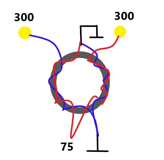
In the above diagram, you can see that the two pairs of wires are different with different colors.
Notice how the wires are wrapped around the core. One end of the red wire represents 300-ohm input while the other blue end represents the other 300-ohm input end.
The end having both blue and red wires is the input GND. On the other side, you can choose any one pair to be the 75-ohm output end. The remaining end will be output ground.
If you have followed the steps correctly, your matching transformer is ready. You can connect the input ends on the antenna and the input GND can be connected to the antenna ground.
*Caution- If you are wanting to connect it to a coaxial cable, make sure that there is no power supply through the cable.
This transformer is a short circuit and if excess DC passes through the cable, the device will be destroyed.
To avoid this accident, you can use a capacitor before connecting it to the cable. You should also take other necessary precautions while working with electrical devices.
Make sure to wear rubber gloves and avoid any contact with water.
We hope that you liked our step-by-step guide on how to make a 75 to 300-ohm matching transformer.
We have tried our best to explain the process most conveniently and affordably.
There are many kinds of matching transformers that you can use in your electrical projects.
We recommend using this 75 to 300-ohm transformer as it is good for small and middle-scale projects.
This can be connected to any kind of receiving antenna if you use a double-hole pig-nose core in place of the toroidal core.
Now, we have discussed a little about matching transformers and also talked about how you can make a simple one for yourself.
So, let’s look at the most frequently asked questions and we’ll try to answer and explain them.
Frequently Asked Questions of How To Make A 75 To 300 Ohm Matching Transformer
What is meant by impedance?
Electrical impedance is the total measure of obstruction presented by the electrical circuit to the electric current.
Impedance includes the measurement of both resistance and reactance.
Resistance arises from the structure of the conductor while reactance arises from the change in electric and magnetic fields when AC is passed through the conductor.
In the case of direct current systems, impedance is almost equal to the value of total resistance as their no change in the field, and hence applied reactance by the conductor is negligible.
Why is matching impedance important?
In many systems, the input impedance remains very high and we cannot work properly with such high frequencies.
So, we need to reduce the impedance to lower frequencies for our convenience.
Complex digital circuits require stable and controlled impedances as it impacts on EMI and causes pulse distortion.
If the impedance is not treated correctly, it can make a negative impact on the circuit.
How does frequency depend on the resistance of a circuit?
The frequency of a circuit increases with an increase in the resistance of a wire or the circuit itself.
But frequency only varies with resistance in an AC system. In an AC system, electricity mostly flows through a small portion of the conductor known as skin depth.
This skin depth varies inversely to the frequency. If frequency increases, then the skin depth will decrease significantly and therefore the resistance offered by the conducting wire will also increase.
Is an impedance matching transformer used in radios?
Impedance matching transformers are used in radios for transferring signals from one circuit to another and lowering the impedance accordingly.
The transformer isolates the two circuits from one another and helps them to function correctly.
Without the presence of transformers, the DC bias conditions would be disturbed and the circuits would not work.
They are also used in several audio devices like loudspeakers or microphones.
Where should I use 75 to 300-ohm impedance matching transformers?
Impedance matching transformers can be used anywhere where you need to match the impedance of two circuits.
These 75 to 300-ohm baluns can be used while working with FM radio (VHF).
The only drawback is that there can be some loss of energy or signal strength while operating with medium wave frequencies. It may cause signals to be distorted.
Between 50 ohm and 75-ohm coaxial cables, which one is the best?
50-ohm ohm coaxial cables are better than 75 ones as the later ones tend to lose more signal strength.
For every 10 feet, 75-ohm cables lose twice the amount of dB gain comparing to 50-ohm cables.
So, if we calculate, we can say that 50-ohm cables are approximately 1.6 times more powerful than 75-ohm ones if the same signal is passing through them.
But, 75-ohm cables are good for homes or places having coverage areas less than 7500 square feet. You might also find 75-ohm cables in your home at many places.
Similar Posts:
- Micropower Broadcasting: A Technical Primer (How to Start a Micro-Radio Station)
- Best Coax For HF Ham Radio (2026)
- 9 Best Dipole Antenna of 2025 – A Comprehensive Buying Guide
- 11 Best Marine TV Antenna Reviews in 2026 – Buying Guide
- Top 14 Best Long Range Omnidirectional TV Antennas in 2026 (Reviews & Buying Guide)
There is a reason why systems that transmit and receive are 50 ohms and systems that receive only are 75 ohms. The ideal impedance for receiving with the lowest attenuation is actually 77 ohms. The ideal impedance for transmitting is around 30 ohms. For systems that do both, 50 ohms is a compromise between the two ideals. 75 ohms for receiving does NOT attenuate more than 50 ohms like you claim or we never would have used 75 ohms for receive only. This was worked out in 1929 by Bell Labs and there is a tremendous amount of data on this subject.